Stress Analysis for Shrink Fitting System Used for Ceramics Conveying Rollers

Article Preview

Abstract:

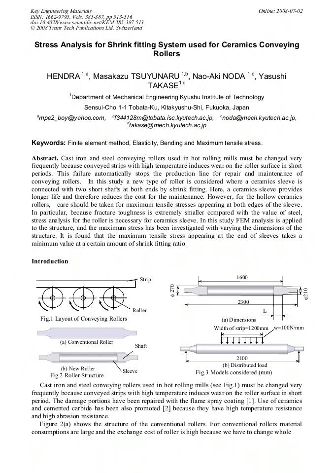
Cast iron and steel conveying rollers used in hot rolling mills must be changed very frequently because conveyed strips with high temperature induces wear on the roller surface in short periods. This failure automatically stops the production line for repair and maintenance of conveying rollers. In this study a new type of roller is considered where a ceramics sleeve is connected with two short shafts at both ends by shrink fitting. Here, a ceramics sleeve provides longer life and therefore reduces the cost for the maintenance. However, for the hollow ceramics rollers, care should be taken for maximum tensile stresses appearing at both edges of the sleeve. In particular, because fracture toughness is extremely smaller compared with the value of steel, stress analysis for the roller is necessary for ceramics sleeve. In this study FEM analysis is applied to the structure, and the maximum stress has been investigated with varying the dimensions of the structure. It is found that the maximum tensile stress appearing at the end of sleeves takes a minimum value at a certain amount of shrink fitting ratio.

You might also be interested in these eBooks

Info:

Periodical:

Key Engineering Materials (Volumes 385-387)

Pages:

513-516

Citation:

Online since:

July 2008

Export:

Price:

Permissions CCC:

Permissions PLS:

Сopyright:

© 2008 Trans Tech Publications Ltd. All Rights Reserved

Share:

Citation:

[1] Miki, E., High Corrosion Resistance and Cost Reduction by Spraying Methods, Plant Engineer, Vol. 21, No. 1 (1989), pp.8-12 (in Japanese).

Google Scholar

[2] Iwata, T. and Mori, H., Material Choice for Hot Run Table Roller, Plant Engineer, Vol. 15, No. 6 (1983), pp.55-59 (in Japanese).

Google Scholar

[3] S. Harada, N. Noda, O. Uehara and M. Nagano, Tensile strength of hot isostatic pressed silicon nitride and effect of specimen dimension, Journal of the Japan society of mechanical engineering, Vol. 57, No. 539 (1991).

DOI: 10.1299/kikaia.57.1637

Google Scholar

[4] H. Kobayashi and T. Kawakubo, Fatigue -Difference between ceramics and metal-, Journal of the Japan institute of metals, Vol. 27, No. 10 (1988).

Google Scholar

[5] Editorial Committee of Ceramic Society of Japan, Material properties of ceramics, pp.34-36 (1979).

Google Scholar

1. 0 2. 0 3. 0×10-4 140 120 100.

Google Scholar

[80] [60] [40] [20] [0] Cemented Carbide Ceramics Steel σθmax [MPa] Steel.

Google Scholar

1. 0 2. 0 3. 0×10-4 140 120 100.

Google Scholar

[80] [60] [40] [20] [0] Cemented Carbide Ceramics Steel σθmax [MPa] Steel σθb [MPa].

Google Scholar

1. 0 2. 0 3. 0×10-4.

Google Scholar

[50] [40] [30] [20] [10] [0] Ceramics Steel Steel Cemented Carbide σθb [MPa].

Google Scholar

1. 0 2. 0 3. 0×10-4.

Google Scholar

[50] [40] [30] [20] [10] [0] Ceramics Steel Steel Cemented Carbide Shrink fitting ratio δ/d Shrink fitting ratio δ/d (a) σmax vs. δ/d (b) σθb vs. δ/d.

Google Scholar

1. 0 2. 0 3. 0×10-4 100.

Google Scholar

[80] [60] [40] [20] [0] σθmax [MPa] ρ ρ=5mm ρ=30mm ρ=20mm ρ=10mm.

Google Scholar

1. 0 2. 0 3. 0×10-4 100.

Google Scholar

[80] [60] [40] [20] [0] σθmax [MPa] ρ ρ=5mm ρ=30mm ρ=20mm ρ=10mm σθb [MPa].

Google Scholar

1. 0 2. 0 3. 0×10-4.

Google Scholar

[50] [40] [30] [20] [10] [0] ρ ρ=5mm ρ=30mm ρ=20mm ρ=10mm σθb [MPa].

Google Scholar

1. 0 2. 0 3. 0×10-4.

Google Scholar

[50] [40] [30] [20] [10] [0] ρ ρ=5mm ρ=30mm ρ=20mm ρ=10mm Fig. 9 σθ vs δ/d when ρ=5, 10, 20, 30 (σθmax = σθs+σθb, σθs: Stress due to shrink fitting, σθb: Stress due to load distribution) Shrink fitting ratio δ/d (a) σmax vs. δ/d Shrink fitting ratio δ/d (b) σθb vs. δ/d E=210GPa E=300GPa E=500GPa.

DOI: 10.1299/jsmekyushu.2008.61.165

Google Scholar